Ignition Principles
The development of the ignition system has, from the very beginning, gone hand in hand with the development of the internal combustion engine. The classic inductive ignition system with contact-breaker points has retained its basic design over many decades. It has however been constantly improved and in the last decade almost wiped out and replaced with the more advanced and precise electronic versions. The electronic ignition basics are based on the contact-breaker system so if you understand how those basics work you will not have problem diagnosing the modern ignition systems.
- Basic principles: When a conductor is brought into magnetic field whose field strength is changing, a voltage is induced in the conductor during this change. In other words if you move a magnet across a coil voltage will be produced in the coils windings. If you however suddenly stop the moving magnet the voltage will disappear. Therefore the voltage will be only produced if you keep on changing the magnetic field ( moving the magnet or the coil). The magnitude of the induced voltage is dependant on the strength of the magnetic field, the rate of variation of the field and the number of winding turns of the coil.
- The above process of electric induction is reversible, i.e. on the one hand electric current can be induced by means of an magnetic field, and on the other hand an magnetic field can be induced by electric current. Every current-carrying conductor produces magnetic field. The magnetic effect of a current carried by a straight wire is relatively small. It can be greatly increased by employing the conductor (wire) in the form of a coil and further reinforcing the effect by introducing a iron core inside the coil. Such combination is known as electro-magnet. This principle is used in the relays, injectors, shut off valves and so on.
- Self- induction: We have seen that when electrical current flows through a coil the coil produces magnetic field(2). But the magnetic field when going through the coil’s own windings also produces current(1). We can therefore say that the magnetic field set up by the current flowing through a coil, produces during it’s build-up, voltage in the windings of it’s own coil. This is known as self induction voltage. This self-induction voltage arising from the build-up of the magnetic field is of opposite polarity to the operating battery voltage. Due to self-induction the build-up of the magnetic field in the coil is delayed. When you first apply current to the coil the voltage must first overcome the (opposite) flowing self-induction voltage of the coil before it reaches maximum full flow and the magnetic field is fully build-up. That is why some time is needed for the magnetic field to be fully “charged”. When the magnetic field reaches it’s maximum the self-induction voltage becomes zero because the magnetic field is not changing anymore, so no self-induction voltage is produced.
- Spark Creation: But what happens when we stop the current flowing through the coil? Since the magnetic field can not exist without current flowing through the coil it now collapses. In other words we now have magnetic field that is changing again ( decreasing), and self-induction voltage is produced once again. This time however, the self-induction voltage is of the same polarity as the battery voltage. Now if the two ends of the coil’s windings are close enough to each other spark will jump across them. This arc is nothing but electrical current which makes its way across the air gap between the two ends. The current flows for a while (trying to sustain the field) until the magnetic field collapses completely.
- So we have a spark but is completely useless for our purposes ( ignition) since is at the wrong place. If we fit an switch to the above coil to operate it, the spark will jump across the switch contacts! Not very practical, is it? So why not create magnetic field with our first coil and put another one next to it with lose ends. The magnetic field created with our first coil will charge the windings of the second one and when we switch the current off in the first one…..the collapsing magnetic field in the second coil must produce a spark between it’s lose ends. Wright! Not quite! The coils have to be “in to” each other. So we shall wind the second coil over the first one and if we introduce an iron core in to the first coil, we have created ourselves a transformer. And this is essentially what the ignition coil is – transformer.
- The Ignition Coil: Iron core with two coils usually wound on top of it and each other, all placed in container full of oil for cooling purposes. When electrical current passes through the windings of the coil heat is produced as byproduct. Most modern coils however are “dry” coils without oil for cooling. So now we have two coils namely “primary” and “secondary”. The Primary is our first coil the one we introduce electrical current to. The Secondary is our second coil that will produce the spark we need to ignite the fuel. When we close the switch electrical current flows through the Primary creating magnetic field. This field cuts across the Secondary windings and voltage is induced during the magnetic build-up. This voltage disappears as soon as the build-up is complete. When we open the switch, the magnetic field collapses. Induced voltage is once again created, this time with reverse polarity. In the Secondary coil of a transformer a voltage is only induced when the magnetic field produced by the Primary CHANGES. The magnitude of this induced secondary voltage is dependent on the strength of the magnetic field, on the rate at which the field varies and on the number of turns of the secondary coil.
- Unwanted Arcing: The ignition coil is in principle transformer and the switch we used up to now is represented by the contact-points in the distributor. The only problem left is the excessive sparking between the points of our “switch” created by the primary when the “switch” is turned off. This will practically burn the contacts very fast and further switching off and on will be impossible. In addition to that, the induced secondary voltage is insufficient for a strong spark, because the collapse of the magnetic field is prolonged by the points sparking. The overcome of this problem is the introduction of a capacitor in to the primary circuit.
- The Capacitor: A capacitor consist basically from two conducting surfaces or plates insulated from each other. The characteristics of a capacitor lie in its capacity to store electrical charge ( energy ) and to release this charge again when necessary. You can compare it somewhat with a car battery, although the capacitor can not store energy for as long as the battery. Just as the car battery when connected to a charger, the initial current flowing through the capacitor is high and the voltage low and when the charging is completed the current is low and the voltage is at is maximum. But how exactly the capacitor will help us combat the excessive sparking between the contacts and increase the secondary spark in the process. We connect the capacitor in parallel with the breaker-points ( our switch). As long as the points are closed the capacitor is out of the game as it is short circuited by them and the current flows through the primary of the coil.
- When the points open, the self-inducted voltage across the primary flows back and charges the capacitor with initial high current and low voltage. As the capacitor is placed directly over the points it takes most from the initial high current to charge and the self-induction voltage is low, therefore spark over the points is much harder to form. This have an effect of sudden interruption of the current at the contacts and thus a rapid collapse of the magnetic field. In other words the capacitor “sucks” the energy from the primary causing the magnetic field to collapse much faster than before as there is less self-inducting current. This quick collapse of the magnetic field results in a high voltage being induced in the secondary winding. But since the magnetic field charges both parts of the coil, in the same way now the primary also have higher voltage across it. This voltage can reach as high as 400V. The capacitor is charged with this voltage.
- Dancing together: After the magnetic field has fully collapsed, the self-induction voltage depletes and charging of the capacitor comes to an end. It has to now retain it’s charge, but instead discharges through the primary windings because it is connected directly to it. The resulting discharge current now flows in the opposed direction to the preceding charging current. As a result, magnetic field is build-up again in the coil but of reverse polarity on account of the reversed direction of flowing current. This magnetic field also collapses when the capacitor has finished discharging and a self-induction voltage is again produced which in turn leads to capacitor charge but this time with opposed polarity. Then the capacitor discharges again through the primary to repeat the process once again. We have therefore, after the points open, an oscillating process, much like a pendulum. When knocked once, it swings to and fro several times converting potential energy into kinetic energy and vice versa until due to resistance forces it eventually stops.
- We can briefly summarize the whole process as follows:
- Points-closed = current flowing through primary and Magnetic field build-up to the maximum.
- Points-open = Magnetic field collapses, charging the capacitor through self-induction. The sharp collapse of the field induces voltage through the secondary as well and it is discharged through the spark plug electrodes.
- Capacitor discharges back to the primary and build-up of magnetic field occurs.
- Magnetic field collapses, charging the capacitor through self-induction.
- Steps 3&4 repeat until there is no more energy left ( due to resistance forces) to charge the capacitor.
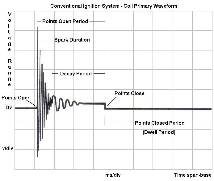
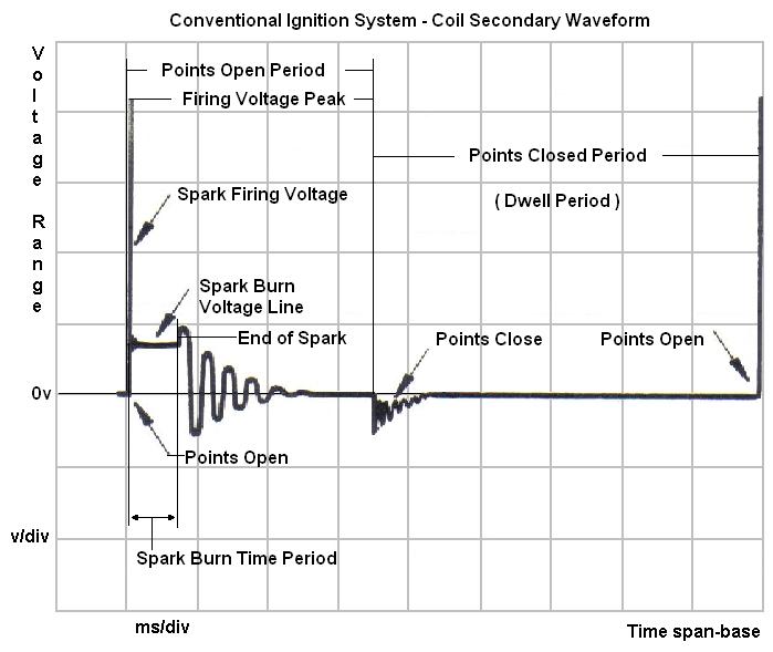
- The oscillating processes in the primary circuit are, of course, also transferred to the secondary winding. The very first pulse of self-induction voltage in the primary ( and secondary) after the breaker-points open is very great, because no spark exist yet and therefore there is no load. When high enough voltage is reached to overcome the spark gap, spark appears. Since this spark is conducting the current from the secondary, essentially it act as a “short” and load so secondary voltage falls and the consecutive oscillations quickly die out. When the energy to support the spark is not enough anymore, the spark extinguishes and no load is more present. The remaining energy left in the coil still continues to oscillate for a while until it eventually also die out. Those last oscillations are called decay process. Then the breaker-contacts close and the whole process starts again.
- So to sum up in very simple words: When the points are closed the coil is charged. When the points open the magnetic field in the coil collapses thus producing surge of energy between the spark plug electrodes. At the next ignition cycle the process repeats again.
- The processes explained here can be easily seen and diagnosed with an ignition oscilloscope. In fact this is the only reliable way to diagnose any problems related to the ignition systems.